

Other than the 'idea' on post #88, I haven't seen any PCB design. Are there any plans for one, or to run any sort of coop?

Ideally yes.. It's thought that it might be run along with a second Ren48LSD and Ren4Flood and RenFlood boards from Brian. The design I thought would look something like the one I posted.. I made that up in KiCAD but that's all.. I'm not fluent enough in all the parts of the board design process and am trying to get some help with that. I think the bigest problem is finding a board house capable of running boards 50cm long.. I've only found 2 so far though I haven't looked extensively..

Cory,
While this will seem like a bit of a fallback from my previous position, but I do think there a great deal of benefit in doing something with that is modular. Phil's modular design would work. The problem with the 50cm boards will be very expensive and I think they are really too close together on that design. I definitely think spacing closer to the 1" is right way to go. Maybe once Phil has his design finalized you could create a version of the Firmware that matched his. I looked at it and was not able to understand it enough to try and convert it.
That said, I would definitely like to see the basic design you created be available for those that want to solder and wired design.
With 1" spacing The tubes would end up being 5ft tall. LOL..
I believe Phil worked it out so they would be just abourt 4ft. The first tubes I ever saw at a local Shopping Mall were 4 and 6 ft. long. I'm being selfish, but I like the 4 ft length. I realize that others have different uses in mind. My use will have them pretty far away from the viewer. That said, the thing I like about your simple design is that the Implementer can do what he wants. Of course, that means that standardized and inexpensive boards could not be done.
I'm using Pegboard for my prototypes and my current spacing is a bit too wide, but it does look pretty good. My prototype is over 5ft tall.
chelmuth wrote:With 1" spacing The tubes would end up being 5ft tall. LOL..
On those boards from the other thread I'm putting the LEDs 0.870" apart (just a smidgen under 7/8"). That might still be too big for some, as the tube protectors that I measured at OSH the other day have about 46" of clear space (plus another 1" or so of opaque cap on each end).
OK I wired up another Tube tonight with the wiring scheme from Phil's idea of the modular boards with 7 LED's each.. This firmware would work with those boards if Phil decides to make a run of them. You can set the fall_count variable to the number of LED's you have.. i.e. four modular boards chained together you would want to set it to 28. Also if you used my original wiring scheme and my original firmware you could set the same variable to any number of LED's if you didn't want to wire up all 56 LED's.
Thanks Cory. Is based on Phil's schematic or his Board layout he later posted. To me, it looks like that Pinout changed significantly when he layed out the second version of his board. I have created a board design to home etch myself based on his schematic, but I don't think it will work. Traces are too close together. I may try to etch one on Monday night when I return from the Rivercamp.
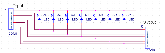
chelmuth wrote:It was based on This Image where input line 1 rolls to line 8 on output.
That is true of both PCB designs.
Is it this one
or
this one .
The first one was 7" long, and had the cathodes connected to pin 1 of the input connector. The second one is 6" long, and has the cathodes connected to pin 5.
Since the second one is even harder to understand than the first one, I'm going to see if I make things work with the first design (compressed down to 6"). The problem that I had with the first one was trace width/spacing. If we go to a PCB coop, the best thing to do would be to go to a two-sided board, and bypass all of the trace width/spacing issues.