

Hi DIYC,
I've just finalized the design of the control system for this year's show. This year I'll be converting an 80-channel LOR setup to DMX and adding about 830 pixels to the show. There are two pixel setups I am looking to implement:
1. 800 WS2811 Technicolor Pixels from Ray Wu with 50 pixels per strand. These will be hung in the bushes up against my house.
2. 30 Pixel "globes" scattered throughout the yard on small poles/stakes. These will be the WS2811 Technicolor Pixels with G40 frosted globes attached. I originally wanted to run DMX to 30 dumb nodes, but I like the technicolor design with the globes, so I'd like to pursue the pixel route here instead.
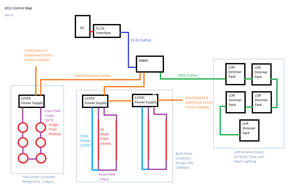
Because the wire runs on this setup will be relatively long distance, I'd like to centralize only the data connections to the pixels, and have multiple 12VDC power supplies local to the pixels. I'm going to attempt to explain the design here, and I have also attached two images for reference. One is a schematic of the whole control system and the other is the design for each power supply that will be distributed in the yard. Please critique if you find a fault in my logic.
A USB-E1.31 adapter will be the main interface with the PC, and a SanDevices E6804 will run the pixels and DMX output. The LOR controllers in DMX mode will connect to the E6804 DMX out, and two pixel outputs will be used to control the yard and bush pixels.
My idea is that anything with a data connection will run on Cat5e cable, while power and combined power/data will run over something thicker. So the E1.31 signal between the USB-E1.31 adapter and the E6804, the DMX signal between the E6804 and the LOR dimmer packs, and the WS2811 signal between the E6804 and pixel power supplies will all run over standard Cat5e (also the data connections between pixel power supplies and between LOR dimmers).
When the 2811 signal reaches each power supply, the signal and power will be combined and outputted over normal 18 gauge pixel cable. Each power supply box (in a tupperware container) will contain a 12VDC power supply, a 120VAC plug to power the transformer, two Cat5 connections (for data in/out), two combined power/data outputs, and one 12VDC power output. I plan to use the 3-pin waterproof connectors that Ray Wu supplies for the 12VDC power out and combined power/data out. I want to have a relatively standard design for each power supply box, so if one fails in either pixel setup, I can easily swap it out for an identical one.
The power supply box would connect to the pixel strands in the bushes in the following manner: one 50-pixel set plugs into the female combined power/data output. A two-conductor extension cable (with the 3-pin waterproof connectors) would connect to the female 12VDC power out, and plug into the strand at the other end. A second set of 50 pixels would also plug into the end of the first strand where the power has been injected. Finally, the end of the second strand would plug into the male combined power/data output of the power supply box. The plan is to have both a male and female 3-pin connector at each end of each 50-pixel strand for maximum flexibility. I think this design is good because the data is redundantly injected in both ends of the 100-pixel set, while power comes in at pixel 1, 51, and 100. This 100-pixel setup will be repeated 7 more times, and the pixel data connection will be daisy-chained between all power supply boxes.
For the 30 globes scattered throughout the yard, I knew I would have trouble with voltage drop, as each pixel will be 10-12 feet from its closest neighbor. So the idea is to have five power supplies scattered throughout the yard, each one dedicated to 6 pixels located nearby. The same power supply box as before will be used in this setup, but here each globe/pixel will have a male and female 3-pin connector attached. Pixel 1 in the loop will connect to the female combined power/data out of the power supply box, and 5 additional pixels will be daisy-chained with 3-conductor extension cables. Pixel 6 will connect to the male combined power/data output to complete the loop. The total distance of the loop will probably be about 70 feet, but I think this should be OK for voltage drop over 18 awg cable, given relatively few pixels. If it becomes a problem, I can always use the third output on the power supply to inject power between pixels 3 and 4. Pixel data running over Cat5e will be daisy-chained between all 5 power supply boxes.
Here are the components I plan to use:
For the yard lights: Technicolor Globe Pixels. Each node will be cut from the strand and given its own male and female connectors. (these)
For the bush lights: 8x Technicolor Pixels. Each 100-pixel strand will be divided into two 50-pixel strands and given male and female connectors at both ends.
For the power supply boxes: 13x 12VDC Power Supplies (+1 additional to power the E6804?)
For the cabling I plan to use vampire cord for the 120VAC inputs as well as the the extension leads from each power supply box (except where data is required). For the 3-conductor cable, I plan to use 3 rolls of this.
And here are my questions:
1. Is it fine to run such a high number of pixels (800) off of a single output of the E6804? I would I be better off with a larger design, such as the E682, and distributing these nodes over several outputs?
2. Is the DMX output of the E6804 reliable enough, or am I better off splitting the E1.31 connection and getting a E1.31-DMX adapter to connect to all the LOR dimmer packs?
3. Am I going to have any problems with data loss if I try to run the pixel signals over such long distances? I believe the DMX and E1.31 signals should be fine.
4. Is there any problem with injecting data at more than one point along a single loop?
5. Is it okay to run only data from the pixel controller and no power at all? Anything I should be aware of here?
6. Are the power supplies I selected suitable for such a setup?
7. Does the design look safe, assuming that I place fuses and waterproof where appropriate? The idea is to make the whole thing as plug and play and interchangeable as possible in the event of a parts failure or future change of design.
8. Will it work? 🙂
Thanks in advance for the help! I look forward to hearing your critiques!
Greg


Without using null pixels or RS485 extenders long data runs will likely cause you problems.
Running local supplies can work well as you can get rid of the voltage loss issues..
This is what I'm doing this year using extenders and power injectors of my own design.
Ahh, that's the one thing I forgot to ask. If I were to build in null pixels, would it be possible to make each null pixel run on its own power supply? So basically I would still only send data over the long runs, but interrupt them every 20 feet or so with a pixel attached to an individual PS. I attached an image to clarify what I'm thinking of doing. If this is possible, I think it would be preferable to voltage loss/grounding issues just trying to get enough voltage to the null pixels (in addition to simplifying setup), as some of the runs will be 60-ish feet. Thoughts?
