LED Curtain for Garage

You may be able to physically cut the matrix in half, but whether it will run again after that is another matter...
 
Would you cut it in the middle to control the upper 1000 pixels with the existing upper connector and control the lower 1000 pixels with the lower existing connector? Then I don't have to solder connectors on, just cut the cable.
The connectors appear to be male/female. Most of us wire male on the input. Using the "end connector" will not work (data will be backwards). You will want to pick up some pigtails that match the existing connector and solder them in.
 
You may be able to physically cut the matrix in half, but whether it will run again after that is another matter...
That's exactly my worry and why I was asking for input. These matrixes are expensive... I would hate to destroy them. Looking at the details, it seems to me that the "main line" on one of the shorter edges is a relatively thick cable consisting of 3 conductors. So must be power and data. From there, there seem to be 4 conductor pebble/seed strings, two power, one data, one backup data. I can't drive the whole 2000 LEDs from one F48 port. At the minimum I need to use 2 ports, 1000 LEDs on each port (500 if I want 40fps, if my F48 v1.04 even supports 40fps). So the idea was, I cut that "main line" to separate the 2000 LEDs into 2x 1000 LEDs. Then I use the upper and lower connector to drive each of the two sections with one F48 differential port, each.

But thinking about this, how does each pebble/seed string know who it is? Pixels can enumerate themselves when they are all in one long string. But this one appears to be 20 strings in parallel. Ray Wu told me each pixel is individually addressable. So somehow they know which one is which. I just don't quite understand how. And will I destroy the matrix, if I cut the "main line"?

@MikeKrebs good point about the female/male connector. I am not too worried about that, though. The lead for the connectors are 20cm so that gives me plenty to work with. I will just cut off one of the connectors and replace it with one of my xConnect pigtails.
 

Attachments

  • MatrixDetail1.png
    MatrixDetail1.png
    301.1 KB · Views: 2
turn on the first 1000 pixels. cut between last on and first off. run data and v- from pixel 1001 back to a port on the controller.
 
Ok, change in plan. Ray Wu is GREAT! I just communicated with him again (he is patient...). He was offering what appears to be a custom size. However, I ended up changing the order to 10 grids each 1m x 1m. That means I will have 20LEDs x 20 LEDs = 400 LEDs per grid. It's a bit more work putting this together and I will now need 10 ports on my F48. But no cutting, no risk from cutting, no changing connectors (I requested the xConnect which I am using), it can run at 40fps, and I still have other ports available as I only use 400 LEDs per port which leaves me with 1024-400=624 LEDs for the other two banks. Me happy, unless I missed something...
 
But thinking about this, how does each pebble/seed string know who it is? Pixels can enumerate themselves when they are all in one long string.
ws2811/ws2812 don't enumerate themselves. They simply take 24 bits of data and pass the rest along. They have no idea where they are in the string or if anything is in front of them or behind them.

Your design change is a god decision.
 
ws2811/ws2812 don't enumerate themselves. They simply take 24 bits of data and pass the rest along. They have no idea where they are in the string or if anything is in front of them or behind them.

Your design change is a god decision.
Well, enumerating was wrong. But as data comes down a string, a pixel takes out the value and keeps it for itself. Then it sends on the rest of the data coming in. So the first pixel takes the first 24 bits (for RGB), the second pixel takes the second 24 bits coming down the string, etc. So it's kind of enumerating.

But as I write this, I think I now understand what's going on. Ray Wu sent me an image of what happens in those connectors on the "main line". So there are the 3 conductors going down the "main lines". That goes down the side of the matrix. Then from that, you see 4 wires going along the pixel string which are the lines going towards the bottom in the image (in my previous image they would go toward the top along the pebbles/seeds so flip it upside/down). So my understanding was wrong. I thought the green "DATA IN" line is fed parallel to each string. Instead, it seems to go down the first string, returns at the end of that string (somehow) and then comes back that 4th conductor. So that would be DATA OUT on the first string. DATA OUT on the first string then goes to DATA IN on the second string, etc. So while power is fed in parallel, the data is actually going in series down all 2000 pixels (on a 1m x 5m matrix with 5cm spacing). That's actually a bit of a concern because that 4th conductor isn't a backup line but a line to feed the signal back to the next string. So I would expect that if one LED breaks, the rest of the matrix will be down. But I guess that's what we had to deal with with all those strings that don't have backup lines. So as @MikeKrebs said, it was probably a good decision to go with 10x 1mx1m so if one LED in a 1mx1m matrix goes down, only part of that 1mx1m matrix goes down.
 

Attachments

  • MatrixDetail2.png
    MatrixDetail2.png
    118 KB · Views: 0
"So I would expect that if one LED breaks, the rest of the matrix will be down"

This happens to 100% of the pixel based props. You WILL need to learn to replace pixels and you WILL need spare pixels around and you WILL need to learn to solder.
 
"So I would expect that if one LED breaks, the rest of the matrix will be down"

This happens to 100% of the pixel based props. You WILL need to learn to replace pixels and you WILL need spare pixels around and you WILL need to learn to solder.
Well, I saw the 4 wires and was hoping that's a backup channel as with the WS2815. It appears that's not the case. I do have a couple of soldering irons (desk and portable), "helping hands" for doing stuff on the desk, tinner, water sealing 3:1 shrink wrap, etc. I am no expert by any means with this stuff, though. Our son is probably doing better with soldering than me.
 
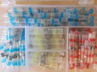
II have moved to the low temp solder inside the shrinkwrap sleeve along with the water sealing beads at each end. Sealed using a heat gun. HUGE time saver.
 
About a dozen years ago Don Julien (djulien) made a matrix on his double garage door using regular LEDs and charlieplexing the darned thing. It also looked like a HUGE amount of work!!! I have no idea how long he used it or even how successful it was. But kudos to you for trying something different. As you're finding out, there can be a rather large out-of-pocket cost to making big display pieces.... the four-house Santa's Village I made took a couple years to pull off and cost a bundle...
 
Are you referring to the ones in the picture? I didn't have much success with them. Even at low temps, the sleeve of the cable starts melting before the solder melts properly and I am not too confident about the sealing, either. But maybe I just bought the cheap stuff. Or maybe I do it wrong. Or both :confused:

Solder1.jpg
 
Yes those. And a heatgun with a directed nozzel and temp control. It took a lot of practice to get it right, but it was worth it.
Hmm, maybe my problem is that I didn't use any of the attachments to direct the heat. While I used the heat gun on low heat and did further adjustment by changing distance, I just used the round opening (no attachment). Maybe not using any attachment is the problem. I have to give this another try...
 
@Mark_M I am not sure I understand the images.
Yes.
View attachment 47654View attachment 47655
View attachment 47656View attachment 47657

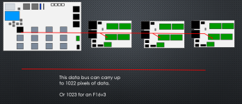
That's the F48 version slideshow, related to this video I did on the F16v3:
Ironically I made the F48 slides up before the F16 and never recorded it for Youtube.... wasted time whoops.


There is a way to get past the 'limit' of 1024 on the Falcons. But I really don't want you to do that.
I figured out the part where you don't daisy chain the differential boards. Basically, each port of the 4 differential controllers that are connected to bank one (red box in your figure) can support the number of pixels/nodes (3x channels) for whatever you set. Lets say x pixels. Then each of the 16 ports (4 differential controllers and 4 controllers per bank) is set to y pixels and for the last bank, you have 16x 1024-x-y pixels. So at the end you have 16x (x+y+1024-x-y)=16x 1024 pixels = 16384 pixels.

What I don't quite understand yet is how the daisy-chaining works. So you can daisy-chain a max of 3 differential controllers together? So I guess in your picture in the bottom right, the first differential board takes port 1-4, the next differential board takes port 17-20 and the last of the three differential boards takes port 33-36? So you can't connect anything to the F48 ports that are lated 17-20 and 33-45 (basically, the 2 ports below the top bank to which the first differential board is connected).

So if the above is correct and I put my sliders at 512, 256 and 256, I get a max of 512 pixels for the first differential board, 256 for the second differential board and 256 pixels for the third differential board? That's not how I put my "differential box" together. I was going to build a box with 3 differential board in it so I can use 10 of the 12 ports for 10 20x20 pixel matrixes. But each matrix has 400 pixels. So if the first differential board is on bank #1 with 400 pixels, the second board daisy-chained to the first board is on bank #2 and also has 400 pixels, then the second daisy-chained board on bank #3 would only have 1024-2*400=224 pixels left while I need another 400 pixels.

So to solve this problem, assuming I have a box with 3 differential boards, I would have to run 3 Ethernet cables all from the same bank which is configured to 400 pixels. None of those differential boards would be daisy-chained.

I have a total of 10x 400pixels = 4000 pixels. With 3 differential boards I have theoretically 4096 pixels. So is there a way to control the 4000 pixels with 3 differential boards using just 1 cable from the F48 to that remote box?
 
Duh about the daisy-chaining. I should have read the user manual for the smart differential board to the end. In my mind, each of the daisy chained smart receiver is taking up one port on the F48 controller. They are just not physically connected to a port (because they are daisy chained) but then those ports would basically be turned off on the F48. But that's completely wrong. You can still use all 12 ports on the F48. All you do is distributing(!!!) the number of pixels/nodes you would have with a single smart differential receiver over 2 or 3 smart receivers. It kind of makes sense as that way the data rate and the overall design of the F48 doesn't change. It really limits the usefulness of what I though daisy chaining can do. And I created a box with a PSU and two differential receivers in it. That makes no sense anymore now, or at least I can't think of why one/I would do that as you should be able to emulate this with virtual strings. Except maybe you can reduce power injection as now you have 8 outputs instead of just 4, i.e. you can make shorter strings, if the design allows it.
 
Duh about the daisy-chaining. I should have read the user manual for the smart differential board to the end. In my mind, each of the daisy chained smart receiver is taking up one port on the F48 controller. They are just not physically connected to a port (because they are daisy chained) but then those ports would basically be turned off on the F48. But that's completely wrong. You can still use all 12 ports on the F48. All you do is distributing(!!!) the number of pixels/nodes you would have with a single smart differential receiver over 2 or 3 smart receivers. It kind of makes sense as that way the data rate and the overall design of the F48 doesn't change. It really limits the usefulness of what I though daisy chaining can do. And I created a box with a PSU and two differential receivers in it. That makes no sense anymore now, or at least I can't think of why one/I would do that as you should be able to emulate this with virtual strings. Except maybe you can reduce power injection as now you have 8 outputs instead of just 4, i.e. you can make shorter strings, if the design allows it.
Yes. Only 4 differential receivers (all on one bank, not chained) is need to get the the advertised 16,384 pixels (almost, technically 16,532).
Banking splits this up by whatever the slider is set to.... the slider sets the absolute maximum number of pixels per port on each bank.
So if you want the max 1022 pixels per port then put all the differential receivers onto a single bank.

Refer to a port as the green connector which pixels are connected to. Not the black RJ45 ports which connects a differential receiver board.

Chaining differential receivers is spreading the pixels per port count across the chain.
All of pixels on ports 1 add up to the maximum amount of pixels assigned to the bank it's on.
E.g. Bank 1 set to 500.
Port 1 on differential A can be a maximum of 500.
Daisy chaining 3 differential receivers splits that 500 pixels across the 3 diff boards on that single port. So the 1st port of each differential receiver board is subsequently called 1A, 1B, 1C because they are all sharing the 500 pixels. Therefore; 1A + 1B + 1C <= 500 max.
Same on port 2. Three diff boards connected get 2A, 2B & 2C naming. 2A + 2B + 2C <= 500.

Daisy chaining diff boards does not set a hard maximum like banking does for the 4 ports each chain has.


Think of it another way:
Imagine you have a power outlet which can handle up to 15A. You can plugin multiple devices until you reach that 15A maximum.
Now imagine you have 4 separate 15A rated circuits. Each circuit you can plug as many devices into up til 15A and the loads do not have to be equal.

Port #1 is like single circuit, and the loads A + B +C cannot exceed the maximum of the circuit.
Port #2 is like another single circuit, and the loads A + B +C cannot exceed the maximum of the circuit.
Port #3 is like another single circuit, and the loads A + B +C cannot exceed the maximum of the circuit.
Port #4 is like another single circuit, and the loads A + B +C cannot exceed the maximum of the circuit.


1723359548280.png
 
Back
Top