

just curios what did this cost you? i am considering one of these myself.

I can't remember the cost of the FM xmitter, but the RDS module was 35 Euros. The rest to install it in the Ramsey box was less than $5.
Hope that helps.
Best,
Al

intwoit2002 wrote:Attached is the file of the modified schematic I did to insert RDS data onto transmitter. I adjusted the level to the lowest level to give reliable decoding without affecting audio.Hope this helps.
Al
Please clarify some things for me. In the pic you have a wire soldered to the 4.7K resistor at R10 and a ground wire soldered to the edge of the board correct? Is the resistor and capaciter you have showing in the schematic in the box with the RDS encoder? Do you have a schematic of these connections inside this box. It is hard to tell from some of the pics. Thanks
In post #15 of this thread there is a schematic of what I did. PM me if you need more info.
intwoit2002 wrote:In post #15 of this thread there is a schematic of what I did. PM me if you need more info.
Sorry, was referencing the other guys thread. What wattage is the resistor or does it matter? What you did looks different that the schematic on their page. I am so confused. This looks like it is using 2 capacitors and a resistor between 22-100 k. I like how he incorporated it in an external box, but am not clear on what he has done. I am electronically challenged.
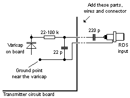
I put together a drawing on how I understand this to be wired. I wanted to put it in a project box with the miniRDS like Jensen1080 did. Even though they are written different I assume that both capacitors are 22 picofarads? Am I anywhere close on this? Now, intwoit2002 did it to R10 with a 3.3 k resistor and a .01 mfd cap. So which is right? Are they both right? Can someone please clarify this?
